I've been tinkering with an Ultra 3000 Sercos drive recently and I've come across a problem, hopefully someone here can shed some light on what I'm overlooking or offer some sort of insight on how this works.
We are trying to set it up to index the servo motor to index on command, but when we enable the drive and start index nothing happens. If we set it to autostart index and select preset 0 it goes about 4 revolutions and then reverses for 4 revolutions, it does this until the drive faults out or we stop it.
Looking at the monitor it shows that both the Forward Enable and Reverse enable are true whether the drive is enabled or not, on top of that no matter what changes we make in Ultraware it doesn't seem to actually make a difference with how fast or which direction the motor is running.
We have 2 digital inputs used, the first one has multiple assignments (Drive enable, preset select 0) and the other is to reset faults.
The servo drive is a 2098-DSD-010-SE and the motor is a MPL-A320H-MK22AA model.
Any help is much appreciated.
↧
Ultra 3000 problem
↧
RSLogix 5000, ADD is not adding
Hello.
A colleague sent me a screenshot (attached) with a peculiar issue. An ADD function that only sends 0 as the outcome, and a DTOS function that only sends " .
I have confirmed that all variables used in the ADD block are declared as integers, and both SumInt6 and String10 are not currently being modified somewhere else.
This impatient colleague is baffled, while I am just sharing this issue in the hopes that someone will eventually come with the simple answer that we are overlooking, or a complex one that we could never hope to realize by ourselves.
Thanks in advance.

↧
↧
PLC for Ham Radio beacon control
I AM NOT A STUDENT LOOKING FOR SOMEONE ELSE TO DO MY ASSIGNMENT FOR ME.
I have the software, cables, etc... and several Allen Bradley SLC's. I'd like to program one of them to run a beacon. I dabble in PLC programming as part of my job, not really a programmer.
I'd like to come up with or copy a way to write values into an algorithm to use a PLC to send a CW message on a beacon station. Starting with some simple stuff, callsign, location, etc... And the perhaps working up to local weather conditions as I have several analog input cards.
I could "brute force" write the rungs for callsign and location but I would rather have some way to use MOV statements or similar to write the required values into counters or whatever to control the CW output.
Any constructive thoughts on this are highly appreciated. I've searched for others doing this but have found very little on this subject and lots of posts about PLC - Power Line Communications.
Thanks,
Jon - kc8fmr
↧
PVP 600 ScreenSaver Change
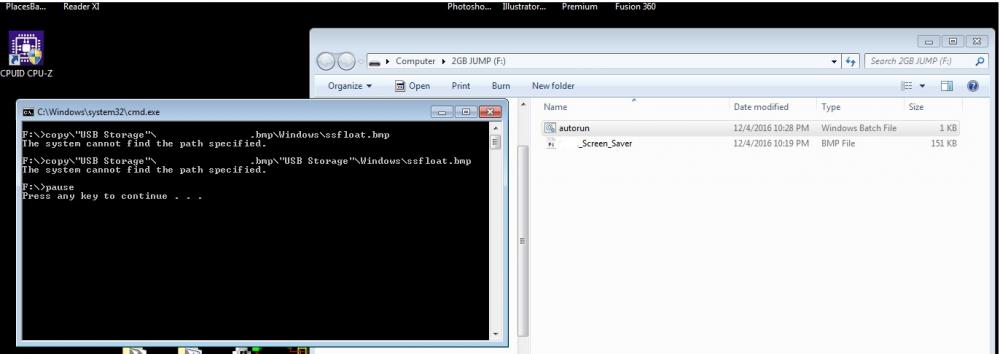
i wanted to change the little bouncy AB logo that comes stock on the panelview 600's to a company logo and in my searching on how to do so i found this on the web and tried to do it today and had no luck. i attached below the error message that im getting when i attempt to do this. looking for some advice as to what i may be doing wrong. when i plug the USB stick into the panelview the error i get is File Not Found, as apposed to the screenshot i attached where i have the USB stick plugged into my laptop. i have the autorun .bat file on the main directory of the usb stick as well as the .bmp file that im attempting to load as the screensaver.
28335 - Changing the Screen Saver Bitmap on PanelView Plus and VersaView CE
Changing the Screen Saver Bitmap on PanelView Plus and VersaView CE
Introduction
A bitmap image may be displayed when the screen saver activates. This image is randomly moved around the screen. By default the terminals have a bitmap named ssfloat.bmp which is used as the screen saver image.
This technical note describes how to change the screen saver image on the following terminals:
- PanelView Plus 400 - 1500 with Windows CE.NET 4.1
- VersaView CE 700 - 1500 with Windows CE.NET 4.1
Note: Previous terminals running an earlier version of Windows CE do
nothave the screen saver
imagefeature (e.g. PV+/VVCE with Windows CE 3.0). On these terminals, when the screen saver is activated, the display back light was simply turned off.
It is not possible to change the screen saver on PanelView Plus 400/600 prior to V3.20.08 firmware.
From 3.20.08 release notes:
PVP400-600, Removed the "system", "hidden" attributes from the
file ssfloat.bmp so that the customer can replace it when it is in the
\windows directory.
Back light Intensity and Screen Saver
For the screen saver bitmap image to be visible, the backlight intensity must be set above 0%. To change the backlight intensity of the PanelView Plus, go to "Terminal Settings" through the main configuration screen. Select "Display" and press enter. Select "Screen Saver." Change the backlight intensity using the arrow buttons.
To change the backlight intensity of the VersaView CE, follow the directions for the PanelView Plus, or open the "display" icon under Start-->Settings-->Control Panel. Click on the screen saver tab and change the backlight intensity.
Format of the Bitmap
- The bitmap can be of any complexity and size. However, a very complex bitmap will use more memory. Also, a bitmap that has a large resolution may either not fit on the screen or will not float around on the screen correctly and will appear sluggish. Therefore, it is suggested that the bitmap be as simple as possible and small compared to the screen size of the unit. Those screen resolutions are as follows:
PV+/VVCE Resolution 400/600 320 x 200 700/1000 640 x 480 1250 800 x 600 1500 1024 x 768 The lower left pixel of the bitmap is used for transparency. When the bitmap appears on the screen, any part of it that matches the lower left pixel will be transparent (i.e. if the lower pixel is black, anything black on the rest of the bitmap will not be visible on the screen).
If a portion of the bitmap is not appearing correctly, the pixel will need to be changed. This can be done on a computer that has Microsoft Paint installed on it. Once the bitmap is opened in Paint, zoom in to the lower left area (approximately 800%), and change the color using Paint tools.
Changing the Default Screen Saver Bitmap to a Custom Bitmap
Create a file on a desktop or laptop computer named autorun.bat. In the file place the following three lines (place the name of the custom bitmap in the place of "oem.bmp"):
copy \"Storage Card2"\oem.bmp \Windows\ssfloat.bmp
copy \"Storage Card2"\oem.bmp \"Storage Card"\Windows\ssfloat.bmp
pause
Place the file autorun.bat on a Compact Flash card and insert it into the external slot on the terminal. The autorun.bat file will automatically be run. Make sure the files are copied correctly by observing the Copied 1 file(s) messages. After completed, close the window by pressing a key or tapping on the X in the upper right.
If using a USB memory stick instead of a Compact Flash card, replace the term "Storage Card2" with "USB Storage" in the batch file. The autorun.bat will not fire on insertion of the USB. Cycle power with the USB storage device in the slot to fire the autorun.bat.
For PV+ 400 and 600 units, it is necessary to reset the terminal in order for the bitmap to be loaded into memory properly.
Return to the Default Screen Saver Bitmap
Create a file on a desktop or laptop computer named autorun.bat. In the file place the following two lines:
del \Windows\ssfloat.bmp
del \"Storage Card"\Windows\ssfloat.bmp
pause
Place the file autorun.bat on a Compact Flash card and insert it into the external slot on the terminal. The autorun.bat file will automatically be run. After completed, close the window by pressing a key or tapping on the X in the upper right.
For PV+ 400 and 600 units, it is necessary to reset the terminal in order for the bitmap to be erased from memory properly.
Alternate Method on VersaView CE Terminals
Another way to change the screen saver bitmap on the VersaView CE is to use the Control Panel. Go to Start-->Settings-->Control Panel and double click the Display icon. Click on the Screen Saver tab, then click on Browse, near the bottom of the window. Use the explorer window to browse to the location of the new bitmap (for example, the compact flash card would be under "Storage Card 2." Select the bitmap and press open. Make sure that the backlight intensity is set to a value greater than 0. Click OK.
↧
Getting UDT to work with physical IO
Greetings,
I'm here in my home lab trying to acquire a working knowledge of UDT's. I've had to work with them in the past in large existing programs and they were a pain to track down and find out what IO they were really controlling. I have a decent understanding of what they are and I've created several to play with here using my softlogix processor and a digital flex IO rack.
My issue starts when i'm trying connect my UDT's to the physical IO. it looks like I cant use a simple move instruction (which would be way too easy and exactly what I need) I have a flex IO 8 point output. Local:1:O.Data[0]
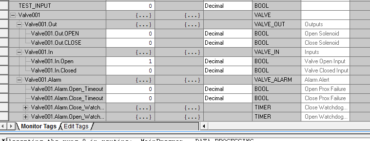
I have a UDT consisting of (see attachment)
Valve001
Valve001.Out
Valve001.Out.OPEN
Valve001.Out.CLOSE
Valve001.In
Valve001.In.OPEN
Valve001.In.CLOSED
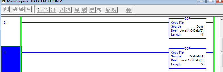
I have a copy instruction set to copy Valve001 to Local:1:O.Data[0] Length 2
that allows the Out.Open and Out.Close UDT's to control bits 0 and 1 of the 8 bit output . .... great.
Now I have another UDT setup to control lighting...
Door
Door.Out.OPEN
Door.Out.CLOSE
I want to control bits 2 and 3
I make another copy instruction in a line before the original copy instruction that states Copy Door to Local:1:O.Data[0] Length 4
but i'm really just fighting for the same 2 bits that the valve controls.... how can I control bits 2 and 3 for the door/lighting logic using these UDT's?
and that's not yet getting into having physical inputs moved/copied to the UDT input bits.
thanks!!
↧
↧
FTView: Global Objects
Hi guys,
I'm working with global object in FTview. I don't know how to enter a constant integer or floating point in Value Cell of "Global Object Parameter Values" Pop-up. I read the manual and it said the value can be any string. Is it impossible to enter a constant number?
And one more thing, is there any way to load the Value of Global Object without Display any screen. I mean, when clicking a global object, it has to be display a certain screen to have option load Parameter Tags. Is there anyway to load parameter tag without loading the screen?
Thank you for you advices!
↧
PanelView 600
Hello all, I'm trying to setup a new PanelView 600 2711-T6C5L1X B F 4.46 I'm trying to connect directly to PC with PanelBuilder 32 and down load an application. I'm having problems communicating with panelview. The panelview is setup for DH485 using the RS232 port. I've tried every transfer type DF1, direct point to point and always get same errors to check cables and make sure printer port is disabled. I'm using a 2711-NC13 cable right from panelview to PC. Am I using the wrong cable?
↧
contador up
Good morning, how to change the 32-bit c5 counters in micrologix 1100, I'm missing a counter up to 300000
↧
Close the window opens with global object
Dear all,
I have a button in global object, and that button that button use to open a pop-up window and transfer parameter tags to that pop-up. The problem is when a click in 2 objects in main window, there will be 2 windows. Is there anyway to close the first window after the second window showed up. Because I don't want have a distract when the first window disappears, then the second window shows up. I came up with idea that i will Abort the first window after the second window showed up, but 2 windows have the same name in FTView designer. So when I did that, the second window was closed, not the first one. I wonder that if 2 windows have different name.
Can you guys give me some advices?
↧
↧
Data highway comm. interface problem
Can u help me guys. I lost my communication from plc5 to dcs bailey infi90. Im using 1770-KF2 as interface. 1770-KF2 XMTG led goes off and the CPU led of KF2 flashes red once in a while. Thanks for your help.
↧
Data highway comm. interface problem
Can u help me guys. I lost my communication from plc5 to dcs bailey infi90. Im using 1770-KF2 as interface. 1770-KF2 XMTG led goes off and the CPU led of KF2 flashes red once in a while. What else can i do to rectify it? I already replaced my KF2 module and done cycling the power of plc processor. Thanks for your help.
↧
PLC5 to DCS comm failure
I lost my comm from plc5 to dcs bailey infi90. Im using 1770-kf2 as communication interface. KF2 module XMTG goes off and CPU led suddenly flashes red once in a while. I already replaced my kf2 module and recycle the power of plc5 processor but the problem is still there. What else can i do to fixed the problem? Thanks for your help.
↧
↧
How can I use FOR instruction for Looping this 24 steps in Rslogics 5000 in ladder?
Can any one tell me how to use FOR instruction in RSlogics 5000 for looping my 36 step runs ...for example I have attached a program containing subroutine having 8 steps in it ...can any one help...?
↧
How Do I Edit PanelView Plus (1000?) File?
How Do I Edit PanelView Plus (1000) File?
Feel stupid asking such a basic question, but they asked me to make a change to this PanelView Plus app here at work (I'm not the "PLC guy' here), and I don't know *how* to open the darn thing. It was hard enough just trying to *find* the app.
I've got two files. One is type "FT View Archive File" and the other is "RSView ME Station File". I tried starting up "FactoryTalk View ME Station" and it brought up a simple panel with "Load Application" and "Terminal Settings" buttons active, but all that seems to do is RUN the panel. Can't seem to edit it that way.
I also see "FactoryTalk View Studio", but when I start *that* up, it asks me to choose an application type to configure (something new?).
There's also something here called "Application Manager" which pops up a dialog with (4) radio buttons for Machine Edition or (3) Site Editions (Local, Network, or Network Distributed). If I select "Machine Edition" and click "Next", there's a button to "Restore Application". Is that what I want to do (to restore the Archive File)????
Why is everything about Rockwell so convoluted and confusing?
↧
Factory Talk issue.
PVPlus 400/600 (320x240)
I am having factory talk version 8.0
and the project which is upload from the machine is done in Version 6.0 and it's giving me this error.
What exactly it's saying I am not getting.
help me for the same.

↧
Micro800 PlugIn Modules Faults
Hello everyone!
I have the quastion about Micro800, and i hope for your experince.
We have a control station based on micro850 plc. Onboard com port using to control some equipment. The first plugIn module is 2080-serialsilos using to send data to main DCS. The second PlugIn module is analog input, and using to collect data from some sensors.
Control station works fine for few months, but now we have a problem. After some time Micro850 is lost connection with PlugIn modules. Second com port is stops responding, and analog parameters are set to EUmin (0 mA), but onboard com port is still work, and i think that problem in backplane BUT If we reboot controller, station work fine, but only for 1-2 hour.
Another version maybe modules go to fault due to high temperature? t~25-30 C
I wanted to check faults in Online mode, but i have project in controller v4.0 and CCW v9.0. I dont want to change firmware in PLC becouse if i make a mistake and station stops working for few days, it wil very bad.
Guys, i need an advice about module diagnostics, why modules go to fault, and where i can get CCW v4.0?
Thank You
↧
↧
AB PLC Firmware or Hardware Producer/Consumer Limits?
Does anyone know if there is a firmware or hardware compatibly issues with producer / consumer tags? I've run into an issue where a newer PLC (version 28.0) works fine with Producer / Consumer tags, however and older (version 16.0) PLC doesn't seemed to want to work. I am trying to chase down the firmware trail and see if there is a compatibly matrix or hardware matrix somewhere that lists some limits or "not support" somewhere.
Is anyone aware of such a thing?
↧
Trouble with firmware update L18-ERM
I have this CompactLogix L18-ERM-BB1B with version 20.001.36 and I am not able to upload or download to it. Logix5000 tells me the offline version file is not compatible with the controller revision. So I try ControlFlash to bring it up to 20.12 or 21.11 and it fails telling me it received an unknown error code. Here's the error in the log file: 12/17/14 14:22:24 [FAILURE] Transfer: Error #11001: Unknown General Status error code received. GS=0x1E 12/17/14 14:22:24 [FAILURE] Transfer: File = C:\Program Files (x86)\ControlFLASH\0001\000E\009B\PN-156514.der, Block = 1.
↧
panelview plus cannot get online tag from plc 5/11 throught ethernet
Hi, I'm new to this. I have plc 5/11 connect to ENI to Ethernet network. I can program the plc through Ethernet no problem, but my PV+ 1000 can't read any tag from plc 5/11. PV+ is also on the network. device short cut is create properly on factorytalk view studio. Prior to this factorytalk view on my laptop can see plc5/11 online but online tag is empty. from one of your post I set up the OPC server then I can get all the online tag. So I add this short cut to my communication for runtime . download to pv+ start it up NOT working. Help, Thanks. Minh
↧