Hi,
Can anyone advise on this problem I am having with a Micrologix 1200 plc, at random times during the run phase (while the machine is running) the machine would stop because the plc has a flashing fault light, i connected to the software of the plc with the laptop and found a fault state inside the plc, reset the fault and continue to run mode, it now works fine, can anyone advise on why this fault mode becomes active or enabled?
↧
Micrologix 1200
↧
Factorytalk view trend & data log
Hello,
I have a question about factorytalk view trend & data log.
2 weeks ago, Data log modem power was failed so HMI control signal wasn't working.
So I recover the power and reboot the plc and download new project file on Rslogix5000.
After that, HMI control signal was working but trend wasn't display(We use live data when display trend)
and 1 data log file was not saved.(We have 3 data log file)
In this situation, what can I solve this problem?
↧
↧
LED status on MLC1200
Hi,
Can someone provide information about function and interpretation of each flashing or steady LEDs on MLC 1200. For example where to look for when Fault LED flashes during normal operation and so on. Thanks in anticipation that someone will help.
Regards
↧
Square Wave Problem With Micrologix
Hello all, this is my first post. I am using an AB Micrologix 1400 (1766-L32BXB Ser C FW 21). I was trying to generate a pulse train using the PTO instruction. I have modified PTOX funct. file. The ladder is just a simple XIO followed by PTO, (The Quick Start ladder from 1766-RM001). When I looked at the output waveform on my oscilloscope, I noticed that it wasn't a square wave. I decided to run it at several different frequencies to see how the wave form would change. At 10Hz i got a square wave. As I increased the frequency the falling edge became sloped and almost horizontal. Is this how the output should behave? The data sheet indicates a max frequency of 100kHz, but at frequencies over 150 Hz. The wave form looks like the output of SMPS.
↧
1734 IA4 confusion
Hello All, I will first state that I am very new to the world of PLC's.
I do the control drawings where I work.
I'm trying to figure out the 1734 Point IO, specifically the 1734-IA4.
I do the control drawings where I work.
I'm trying to figure out the 1734 Point IO, specifically the 1734-IA4.
The manual states "Module power is supplied from the internal power bus".
Does this mean I do not need to run ANY power wires to the modules?
The installation manual shows points 4,5,6 and 7 as "L1" wires??
Does this mean I do not need to run ANY power wires to the modules?
The installation manual shows points 4,5,6 and 7 as "L1" wires??
The system I am designing, from left to right has the following:
1794-PS13, 1734-AENT, 1734-FPD, Followed by Qty. 11 1734-IA4's.
I'm bringing 120VAC and 24VDC to the 1794-PS13.
From the 120VAC terminals, I run wires to the FPD.
From the 24VDC terminals, I run wires to the 1734-AENT.
On the first 1734-IA4, I would think I should bring any power there, because its already back plane fed...….correct? Or DO I run power wires there? Thanks in advance
↧
↧
Communicating a omron nj101 with a SLC 5/04
Afternoon all,
I am trying to transfer data from a nj101 omron plc to a slc 5/04 using rs232. I have a CJ1W-SCU22 serial module on the nj side connected to a 1746-BAS module on the slc side. I have connected and programmed to the 1756-bas using hyperterminal but no matter what command I use I cant extract the specified data from the nj101. I have not been able to find any examples of this online and was wondering if somebody could give me some tips or point me in the direction of any manuals or examples I should use.
Thank you
↧
Hi, trying to upload program from AB 1400, shows no response from processor path/node
Hi, after implement the following steps to configure my Allen Bradley 1400 programing logic controller, I tried uploading program from the PLC, a got a notification displaying (no respond from processor at selected path/node) please will appreciate any help to rectify this error
↧
Micrologix1200 - unable to go online
Hello,
I programmed several Micrologix 1200 (all the same version ) with RSLogix500 (4.00.00.60)
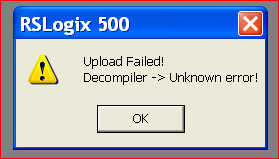
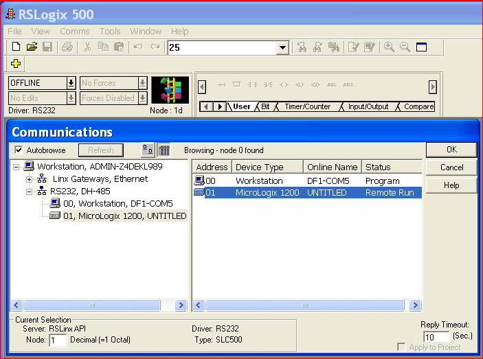
But the last one gives me an error message when trying to go online:
Upload Failed!
Decompiler -> Unknown error.
I see the ML1200 in RSLinx and RSLogix500, the only difference is that is "untitled" (see attachement). Could that be the issue?
I also toggled the COM push button, with noo result.
Any help would be appreciated.
I already browsed older topics on this site, but with no result.
Regards,
Natascha

↧
ControlLogiX 5581E – Memory Dump and Binaries
I had two esoteric question I was curious if anyone might be able to help with.
First, I am playing around with way to monitor the internals of a PLC and I was curious if anyone has any idea on why to pull the internal memory off a ControlLogix 5580. Ideally, I would like to avoid just directly reading the config out and reading individual tags. I prefer to be able to get a little deeper. Something similar to the crash dump, the RSlogix software can generator or something like the S7dump.exe tool for the S7 PLCs i.e. getting at the actual memory in specific memory addresses.
Second, I was curious if anyone knew anyway to grab the actual binary are sent over to the controllogix after the RSLogix 5000 processes a configuration file. In this case I am looking for something similar to the binary files in codesys not the project file. This might be an assumption. Maybe RSLogix doesn’t ever produce anything like that but I figured I would ask
↧
↧
Having issues going online after uploading from AB 1400
Hi, i uploaded program from my Allen Bradley 1400 PLC. when i tried to go online, a notification pops up showing program in processor has changed causing offline state do u want to upload, when i upload the same information comes up
↧
I/O's Read/Write from Micro850
Hello,
I'm using Allen Bradley Micro850 , 2080-LC50-24QWB.
I wrote a program using Connected Component Workbench which reads certain indications and controlling contactors.
My customer would like to connect that PLC to a PC by an Ethernet cable RJ45 and read those input registers and write those output registers into his application that he had built.
He would like to know the commands in order to read or write the data and the TCP/IP data structures and frames.
I would like to have the registers mapping of this PLC as well.
i have been searching this information in the data sheets and have found none.
i hope you could help me or at least instruct me becasue that's really urgent.
thanks in advance.
↧
Cleanup SFC chart
I have been given a task to insert a couple more steps into a RSLogix v.20 SFC routine somewhere right in the middle of a chart with about 60 or so steps.
Just wondering if there is a quick way to 'auto generate' or 'make it look pretty' afterwards without moving and re-drawing every item?
Thanks for your insights..
↧
Connecting multiple RS-232 devices to the same PLC
Does anyone have any experience with sending multiple RS-232 devices to the same PLC? My current set up has 2 RS-232 devices sending raw ASCII data to a 2-port Comtrol DeviceMaster EIP-2202 where it is then sent to the PLC via Ethernet/IP. The problem is that now I need to add three more RS-232 devices. Without buying more DeviceMasters, is there a way of adding the 3 extra devices to where the data from each device can be read separately?
I know RS-232 is 1 to 1, but is it at all reliable to use a multiplexer? I've looked into and I think it MIGHT work, but I'm a little nervous about adding the extra complexity.
Another option I was looking into was to somehow convert multiple RS-232 connections to a single RS-485, which from my understanding can support multiple command and listening devices and I would need to be able to address each different device. My comtrl supports RS-232/422/485.
Thanks for any help!
↧
↧
Changing AB 1756-L73 to L74, L75, etc.
Hello,
I was wondering what the viability and ease of upgrading an AB processor to the next more "powerful" version. Is it a simple plug and play task, or does it require any significant modification to your project to change?
My current project is critically faulting the processor in periods of heavy use so we are considering trying the upgrade route.
On a side note, when viewing the task monitor pie chart in Logix Designer. What does the "comms" portion refer to?
↧
Panelview 1000 does not display correct input
Hello I would like to first let everyone know I am new to the world of troubleshooting or programming plc's . What we have is a SLC500 system that is connected to a Panelview 1000 HMI via the DH+ network. The issue we have is the panelview displays a gate that is suppose to be closed at as gate fault. When i connect to the plc the ladder rung shows that the gate is closed. To show various positions of the gate the programmer used N13:70 as gate opened and N13:71 as gate faulted and N13:72 as gate closed. When i checked the logic it showed the bit N13:72 as engaged or true if you will. This logic is in the ladder rung that is labeled PV Status which i take is the status the HMI reads so my question is why does it show GF when it should be reading GC. Ive searched all through the logic and it doesnt appear to be wrong here is the logic the best I can simulate it
ladder 6 rung 53 instruction is XIC O:13.0/11 and OTE N13:76/0 (Gate Open ) and the branch is XIC I:5.0/11and OTE N13:76/1 (Gate Fault) next branch is XIC N13:3/11 and OTE N13:76/2 (Gate Closed which this section is green or highlighted or true which ever you like)
when i looked at the input XIC N13:3/11 this is what I found is that this XIC is on ladder four rung10 and has the following
XIC T4:154/DN and branchoff that is XIC I:5.0/11(gate opened)XIC I:6.0/11(gate closed) which these two inputs are false or not lighted the output is OTL N13:3/11 and it is true which makes the previous rung true showing the gate closed. So why is the panelview showing the wrong position. I even went as far as resetting the HMI and the PLC so if anyone has a helpful hint I would greatly appreciate it.
↧
indirect addressing of individual bits of a tag of datatype dint using PLC ladder
Hi All,
I have a question on if its possible to do indirect addressing of individual bits of a tag of datatype dint in studio5000 ladder logic?
I am writing a routine that should loop through the individual bits of the tag of data type dint and do processing .
Like instead of using OTE instruction ConfirmRequest[rvIndexSafety]
where confirm Request is BOOL[32] elements
if condition true and rvIndexSafety =1 => it will set confirmRequest[1]
I need to use DINT and set DINTDataType.1
How can i approach this?
Thanks,
↧
bUs error on Yaskawa P1000 Ethernet VFD to Controllogix
Good Day,
I am seeing intermittent bUs (communication bus) errors on 3 VFD's simultaneously. These are Yaskawa P1000's with CM092 Industrial Ethernet Cards.
There are Stratix 5700 switches between the drives and the Controllogix 1756-L75 CPU. Happens every day to every week -- intermittent.
Reading parameter F6-98, it indicates a 'connection time out'. I don't understand why I would receive this fault. IGMP snooping and querier are enabled on all switches, if that matters.
I do not have unicast checked but Yaskawa said that didn't matter. Packet time is 100 milliseconds. I welcome any input on what might cause this. One Yaskawa tech said I should set speed to 100 Mbps (now set at 10 Mbps).
Any help appreciated.
↧
↧
Connected Components Workbench
First time using Connected Components Workbench and am modifying an existing program, does anyone know why and how the original IO_EM_DI_ numbers have been changed and not just the alias'. When I right click and select properties for each tag it gives the address and says 'Read only cell' generated by the I/O wiring tool indicating the I/O channel to which the variable is wired'
Any help would be great thanks!

↧
RSS to PDF Converstion Support Please
Hi Everyone:
I'm Pablo Velazquez from CDMX-Mexico (new on this PLC forum) , I have trying to convert a .RSS file to PDF for a while with no succcess so far  . I have no longer access to RSlogix SW.
Just wondering if someone please support me to convert the .RSS file attached to .PDF.
Thanks in advance for your time and support on this request.
Pablo V
↧
Simliar Mitsubishi functions in Allen Bradley
Hello, I would be really thankful if someone could help me .
Recently, I start using Allen Bradley PLC and HMI. Before, I used most of .
I have difficulty in seeking some similar Mitsubishi functions in Allen Bradley.
- First, I don't know how to switch HMI screen by using instruction in Allen Bradley PLC.In Mitsubishi PLC, I can do that by move a number to base screen register D0.
But I can't find the similar register/tag in Allen Bradley.
- Second, I don't know which bit, relay, timer, counter, register will latch it's value when power turn off. In Mitsubishi, I can know that by looking at FX parameter.
May anyone give me favour, thanks.

↧